1u jbod | octopode
28 May 2025 - harry
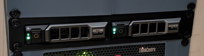
I wanted to add harddrives to my 10” mini rack, but didn’t like any of the existing options. I made this bay which will hold two 3.5” hard drives using dell server caddies. There is a custom pcb backplane that the drives connect to and circuits to drive the connection and activity LEDs.
Off the shelf options
I had a fairly picky set of requirements for adding storage. I’d already decided that I needed a JBOD (just a bunch of disks) and was going to connect it to my mini-pc (thinkcentre m720q) using an lsi hba so I was just looking for a good way to hold and power the disks.
In rough order of priority:
- 10” - of course as my rack is only this wide
- Enough storage for the next few years (I expect around 4TB will be enough)
- Must have blinky lights - this is a server rack afterall!
- Quiet - my server rack is in the living room next to the tv (no, there isn’t anywhere else I can reasonably put it)
- Needs to be reasonable cost
- Fits in 1u space (I only have 8u to play with in total and I have plans for the rest)
- Needs to look good.
- Easy to sway to swap drives - to prevent me procrastinating when a drive dies.
Having listed those lets look at my options.
First, there’s this 3d printed 3.5” drive holder (printables link). I think this is a nice simple design, but it’s fairly compromised in terms of the blinky lights, and easy way to swap drives.
Next, I saw that it’s quite common to get these 4x 2.5” disk 5.25” hot swap cages (example) and 3d print a rack mount. This scores highly on almost all the measures apart from cost. I’d have to use SSDs with this which increased the cost per gb a little to much for me, and the holder itself is around £90ish and difficult to get hold of in the UK.
Editors note: Only now when I’m writing this blog I’ve found pretty much what I was trying to make (apart from the blinky lights) of course this would happen… You’ll have to take my word for it that I didn’t copy this design. I think it’s really quite good, but I’m still glad I made mine and I think it has a few advantages over this one. My custom backplane enables blinky lights, and there’s a fan to draw air over the drives the passive cooling in this design is probably fine though.
There’s also someone on reddit that sells a custom-made 5 bay 3.5” drive holder that uses a premade backplane you can readily get from AliExpress. This is another good option, but takes up too many rack units as doesn’t have my blinky lights!
At this point I decided that I’d have to make my own. I was pretty confident that I could do the 3d modelling but not sure about making the backplane. While I’d designed a few PCBs in the past, I’d never designed anything high-speed (SATA is 6gbps!) and didn’t know how easy it was to drive the activity LEDs.
The design process
The first question I had to answer was, will two caddies even fit side by side within 1u of 10” rack space? The answer is barely, there was about 10mm horizontally spare in total, in which I had to fit all the walls.
Then I had to work out how to actually drive the activity LEDs. You can helpfully very easily find the SATA III specification online. In it, on page 187, you can find this helpful-ish schematic for a driver circuit:
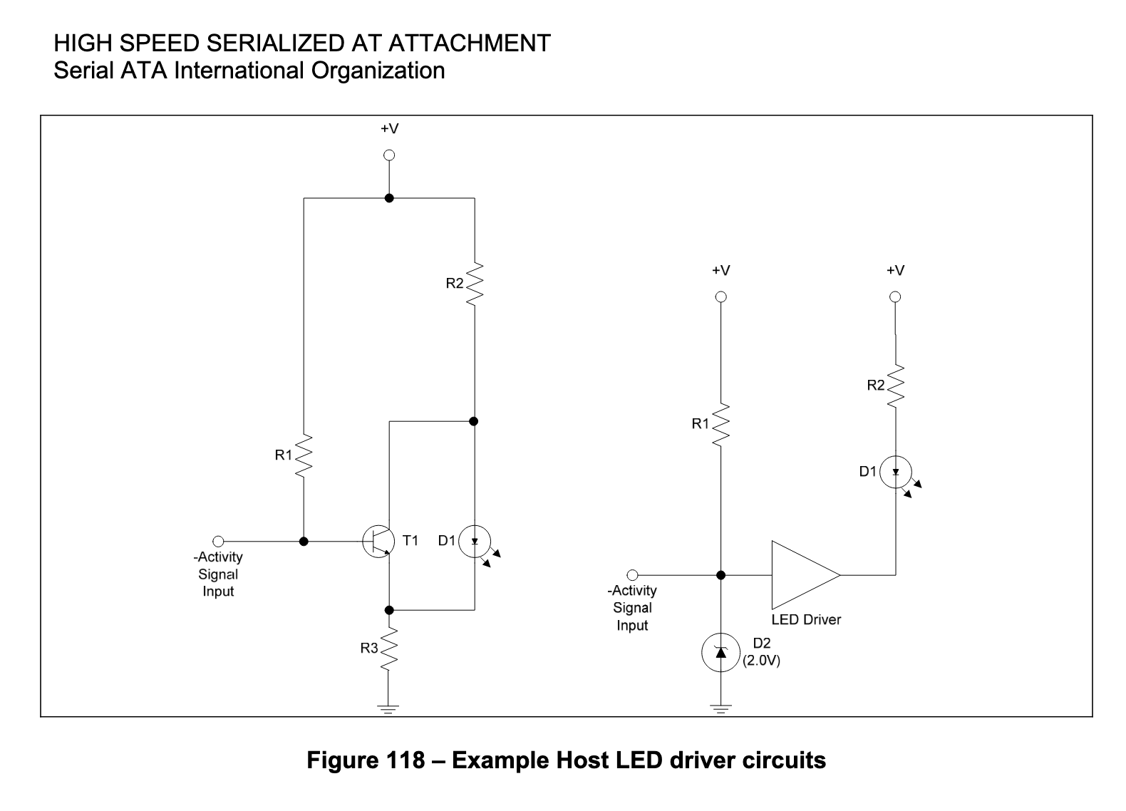
There’s two designs here, and I picked the left-hand because I didn’t know in particular what kind of “LED driver” the one on the right wanted. The tricky constraint that this circuit operates under is that the activity signal pin (pin 11 on the power connector) can only sink 300uA of current, but a typical LED will need around 1mA to run. The answer is to use a transistor to drive it instead. I simulated the circuit on my favourite online circuit simulator https://www.falstad.com/circuit/ to work out the values for the resistors within these constraints.
That being done I stated designing a PCB in KiCAD while pouring over guides for how to design high speed PCBs. I intially went with a 2 layer PCB (trying to save a bit of cost) and promptly got torn apart for this choice on the printed circuit board subreddit. So I changed to a 4 layer board.